How to Calculate CFM Requirements for Your Finishing Space
June 4, 2026
Selecting the wrong airflow capacity for a finishing environment creates measurable consequences: inadequate solvent evacuation, elevated flammability risk, inconsistent coating results, and regulatory non-compliance. Many shops discover airflow deficiencies only after installati
Selecting the wrong airflow capacity for a finishing environment creates measurable consequences: inadequate solvent evacuation, elevated flammability risk, inconsistent coating results, and regulatory non-compliance. Many shops discover airflow deficiencies only after installation, at which point corrective measures are expensive and operationally disruptive. Getting CFM requirements right before specifying equipment is a foundational step in any finishing system design.
This post covers the primary variables that determine CFM requirements for finishing spaces, the calculations used to size airflow capacity, how booth type and application method affect those numbers, and the regulatory thresholds that set minimum performance standards. Understanding these factors allows engineers and facility managers to specify equipment with precision rather than approximation.
What CFM Measures and Why It Matters in Finishing Environments
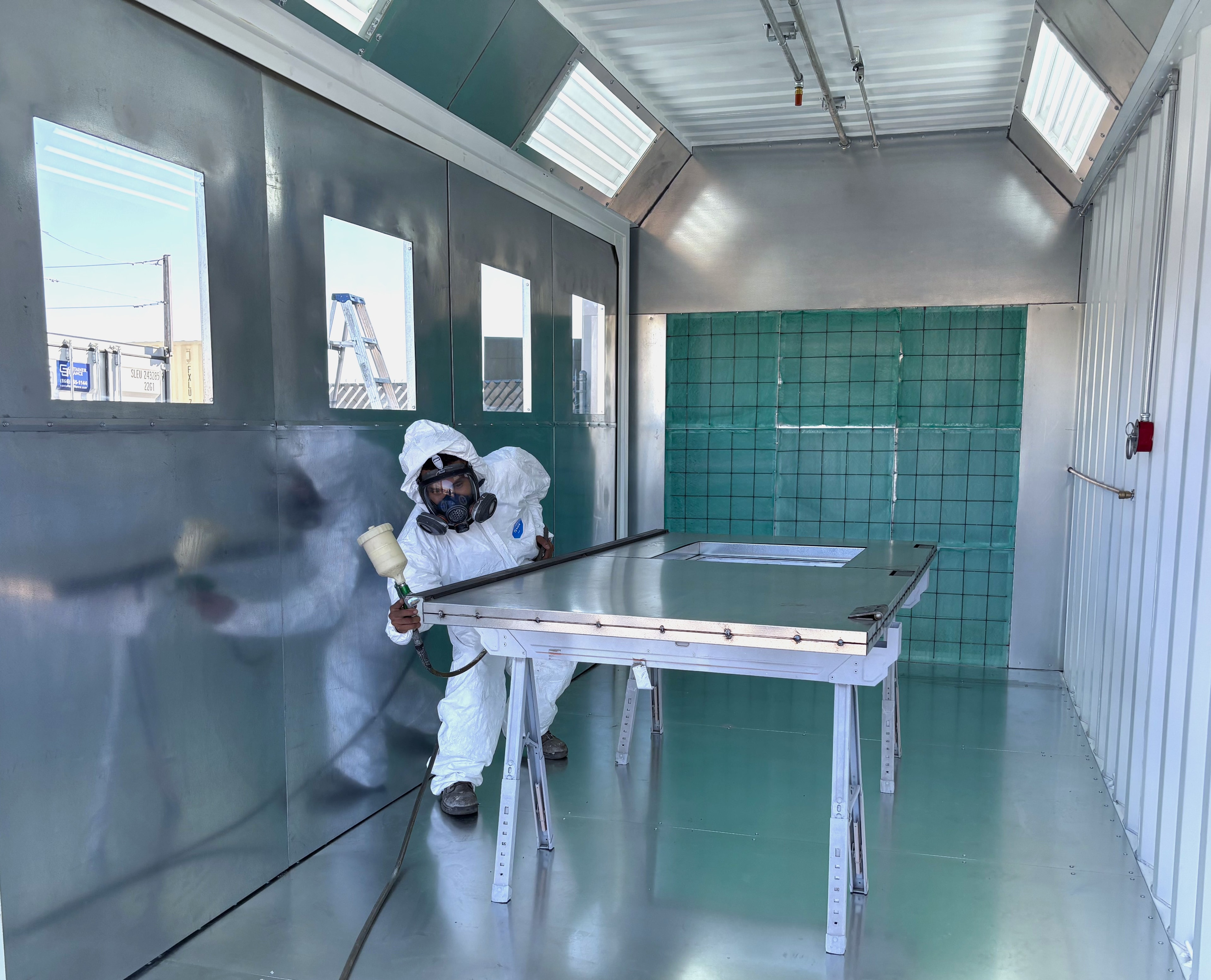
Cubic feet per minute (CFM) quantifies the volume of air moving through a finishing space within a given time interval. In spray booths and finishing rooms, adequate CFM serves two functions: controlling airborne overspray and evacuating solvent-laden vapors below the Lower Explosive Limit (LEL). Airflow that falls short on either measure creates safety and quality failures simultaneously.
- CFM defined: the volumetric flow rate of air, measured as cubic feet passing a given point per minute
- Overspray control: sufficient air velocity carries atomized particles toward exhaust filters before they settle on surfaces or recirculate
- Vapor evacuation: solvent vapors must be diluted and exhausted to maintain concentrations below 25% of LEL per NFPA 33 requirements
- Face velocity: the speed of air entering the booth opening, typically measured in feet per minute (FPM), is directly derived from CFM and booth opening area
- Pressure relationship: CFM balance between supply and exhaust determines whether a booth operates at positive, negative, or neutral pressure
The Core CFM Formula for Spray Booth Sizing
The baseline calculation for a crossdraft or downdraft spray booth begins with the booth's interior volume and the target air changes per minute. For open-face booths, the calculation pivots to face velocity across the opening.
- Volume-based formula: CFM = booth length (ft) × width (ft) × height (ft) × air changes per minute (typically 0.5 to 1.0 for most finishing applications)
- Face velocity formula: CFM = booth opening area (sq ft) × target face velocity (FPM); OSHA and NFPA 33 generally cite 100 FPM as a minimum for open-face booths
- Target air changes: liquid spray applications typically require 0.5 to 1.0 air changes per minute; high-volume or waterborne coating applications may require higher exchange rates
- Conversion check: once CFM is calculated, verify face velocity at the booth opening falls within the 60–150 FPM range to avoid turbulence that disrupts atomization patterns
- Safety margin: add 10–15% to calculated CFM to account for filter loading, duct friction losses, and equipment aging over time
Booth Geometry and Configuration Effects on Airflow Demand
Booth geometry directly affects how airflow distributes through the finishing space. A crossdraft booth moves air horizontally from intake filters to exhaust, while a downdraft booth draws air vertically from plenum ceiling to floor grating. Each configuration produces different velocity profiles and requires different CFM strategies.
- Crossdraft booths: simpler ductwork but less uniform velocity distribution; overspray can pass the part before full evacuation occurs in larger booths
- Semi-downdraft booths: air enters from the ceiling near the front and exhausts through the rear floor; lower installation cost than full downdraft with improved flow over the part
- Full downdraft booths: most uniform airflow across the part surface; highest CFM demand because the entire floor area functions as the exhaust plane
- Booth length factor: longer crossdraft booths require higher CFM to maintain minimum face velocity at the far exhaust wall
- Plenum design: supply plenum depth and filter distribution affect velocity uniformity; undersized plenums create high-velocity channels rather than laminar flow
Application Method and Coating Type as CFM Variables
The spray method and coating chemistry in use directly influence the volume of solvent or carrier vapor released into the booth atmosphere. These variables are not optional inputs in a CFM calculation — they determine whether the baseline volume-based formula is sufficient or requires adjustment.
- HVLP spray guns: operate at lower atomizing air pressure but still generate significant overspray; CFM requirements are comparable to conventional spray in most booth sizes
- Airless and air-assisted airless: higher transfer efficiency reduces airborne overspray but high-VOC coatings still require full exhaust capacity for vapor control
- Waterborne coatings: require higher air exchange rates than solvent-borne coatings because water vapor must be managed alongside any co-solvent content; some waterborne systems require supplemental heating to maintain evaporation rates
- Powder coating: no solvent vapors; CFM requirements shift to particle capture efficiency rather than LEL management; booth design priorities differ substantially
- Multi-gun or automated application: simultaneous spray sources multiply solvent vapor generation; CFM calculations must account for total combined output, not individual gun ratings
Regulatory Minimums That Establish CFM Floors
CFM calculations do not occur in isolation from regulatory requirements. NFPA 33, OSHA 29 CFR 1910.94, and local air quality management district rules establish minimum performance thresholds that calculated CFM values must meet or exceed.
- NFPA 33 Chapter 7: requires spray areas to maintain solvent vapor concentrations below 25% of LEL during spraying operations
- OSHA 1910.94(c): specifies minimum airflow of 100 FPM across booth openings for open-face spray booths
- EPA Method 24: governs VOC content of coatings and affects how much vapor load the exhaust system must manage
- Local AQMD permits: many California air districts require engineering calculations demonstrating compliance before issuing operating permits; CFM values must be documented
- UL listings and equipment ratings: fan and motor ratings on certified booths reflect specific CFM outputs; modifying ductwork or filters without recalculating can invalidate both ratings and compliance
Pressure Drop, Duct Losses, and System Efficiency Factors
Calculated CFM at the fan does not equal delivered CFM at the booth. Resistance from filters, ductwork, transitions, and discharge configurations all reduce effective airflow. Accurate sizing accounts for total system pressure drop, not just the booth volume formula output.
- Filter resistance: clean intake and exhaust filters create a baseline static pressure drop; as filters load with overspray, resistance increases and CFM delivery decreases
- Duct length and diameter: longer duct runs and undersized diameters create friction losses that reduce fan output; duct design should follow ASHRAE or AMCA standards for industrial exhaust systems
- Transition losses: abrupt elbows, reducers, and poorly designed transitions add equivalent duct length; use sweeping bends and gradual transitions where possible
- Fan curve selection: fans are rated on a performance curve relating CFM output to static pressure; the operating point must fall on the efficient range of that curve
- Altitude correction: facilities above 2,000 feet elevation must correct fan CFM ratings for reduced air density; standard sea-level ratings overstate actual volumetric delivery at elevation
Summary
CFM calculation for a finishing space integrates booth geometry, application method, coating chemistry, regulatory minimums, and system pressure drop into a single defensible number. Treating any one of these variables as optional produces equipment that either underperforms on safety and air quality or overshoots capacity and wastes energy. A systematic approach to airflow sizing, validated against NFPA 33 and OSHA standards, is the baseline for any compliant and functional finishing installation.
Why Choose California Pulse for Spray Booth and Finishing System Design
We engineer spray booths, curing ovens, and complete finishing lines to specific CFM requirements, not to catalog defaults. When a project involves complex geometry, high-volume application, or California AQMD permit requirements, we develop airflow calculations based on actual booth dimensions, coating chemistry, and production throughput — then build equipment to match those specifications.
We manufacture direct, which means our engineering team is involved from initial specification through commissioning. Customers receive documentation supporting both equipment selection and regulatory compliance, including airflow calculations, fan curve data, and filter specifications. Contact us to discuss your finishing space requirements with engineers who size systems from first principles.